The Story So Far
Where it started
SpotterBoard didn't start as an LED matrix project at all. The first version was a lot closer to a FlightRadar24-style spotter display — a screen sitting on a desk showing whatever aircraft happened to be overhead. That first build used a 5-inch IPS capacitive touchscreen: sharp, colourful, touch-responsive, everything you'd want from a proper little display.
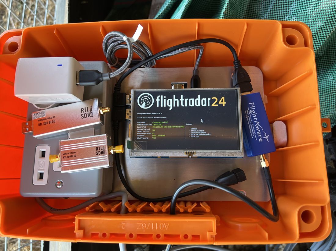
And it worked. But something about it felt... expected. A flight tracker on a small touchscreen is a well-worn idea — it's basically what FlightRadar24's own app already gives you, just running on a dedicated screen instead of a phone. It did the job, but it didn't feel like a build. It felt like an app in a box.
The switch to LED
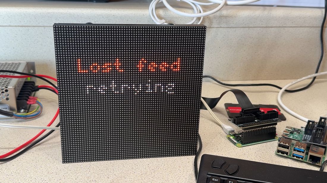
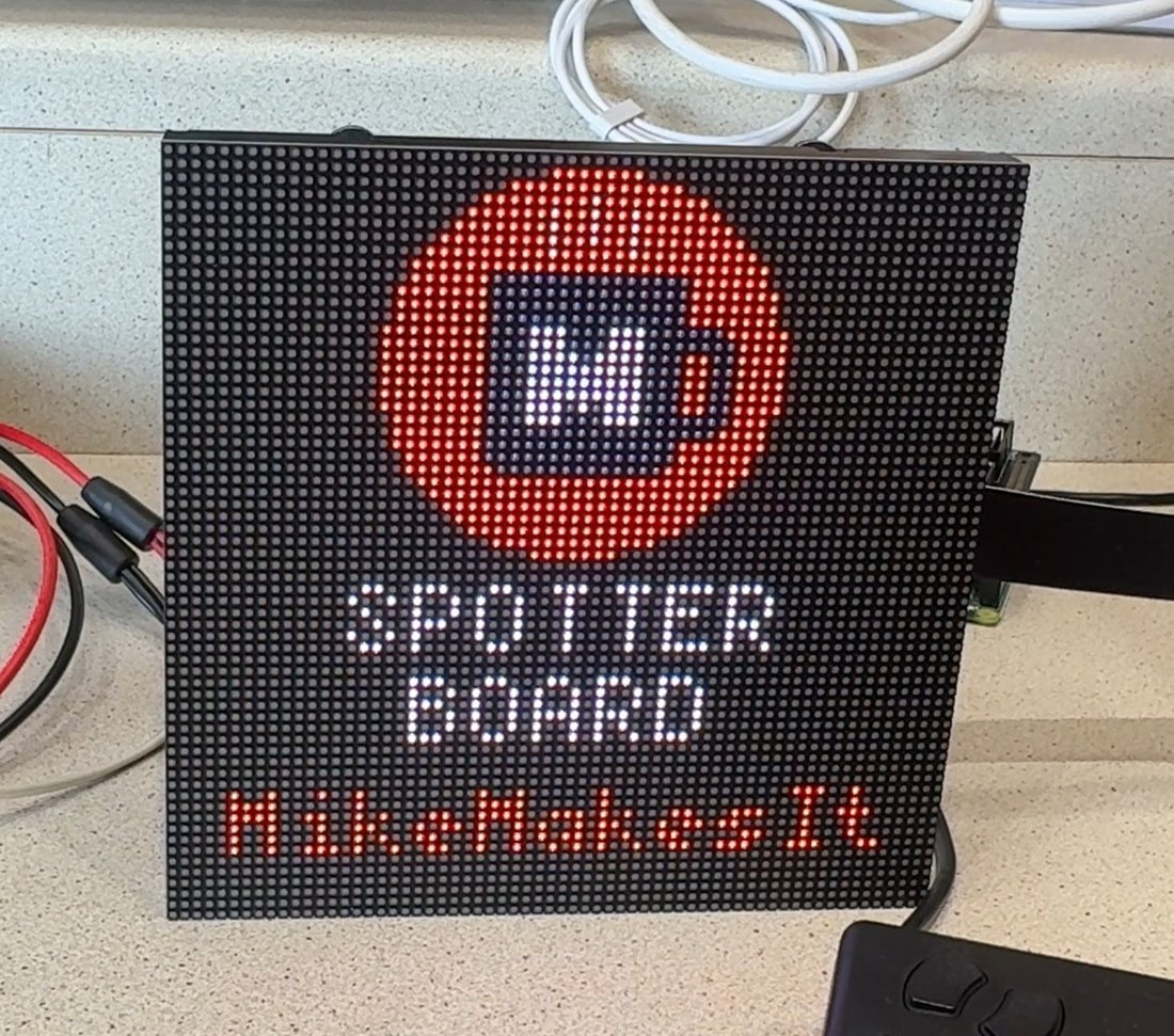
The move to a 64×64 LED matrix panel changed that completely. There's something about the aircraft data rendering out in blocky, glowing pixels — the callsign, the altitude, the climb or descent — that feels more like a piece of hardware and less like a screen. It's got presence. It looks like something built specifically for this one job, rather than a general-purpose display pressed into service.
It's also just a better fit for the actual audience. Plane spotters and Raspberry Pi tinkerers aren't chasing the smoothest, highest-resolution display — they're drawn to things that feel handmade, a bit retro, a bit chunky. The LED matrix leans into that instead of fighting it.
What's actually running underneath
Behind the display, SpotterBoard pulls live ADS-B data — the position-broadcast signals aircraft transmit constantly — from public aggregators like adsb.lol and adsbdb.com, and renders it out in real time: callsign, altitude, speed, route, whether the aircraft's climbing or descending. It runs on a Raspberry Pi (4, 5, or Zero 2 W, depending which one you've got spare) driving the panel through an Adafruit RGB Matrix Bonnet.

Some of the trickier problems ended up being less about the flight data and more about just keeping a small embedded device reliable — things like automatically detecting when the data feed drops out and showing a "Lost feed / retrying" message instead of silently freezing, or making sure the boot screen actually displays "SPOTTER / BOARD" perfectly centred regardless of which font characters happen to be wider than others. Small details, but the kind that separate a demo from something you'd actually want sitting on a shelf.
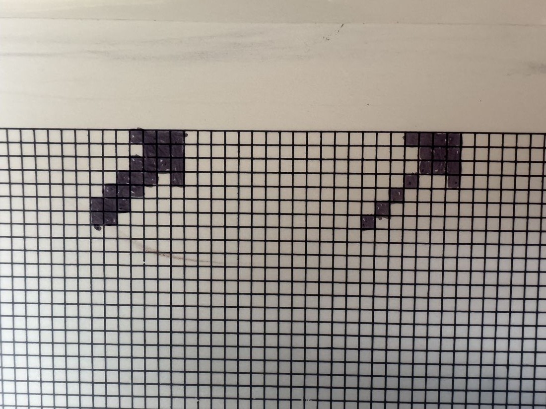
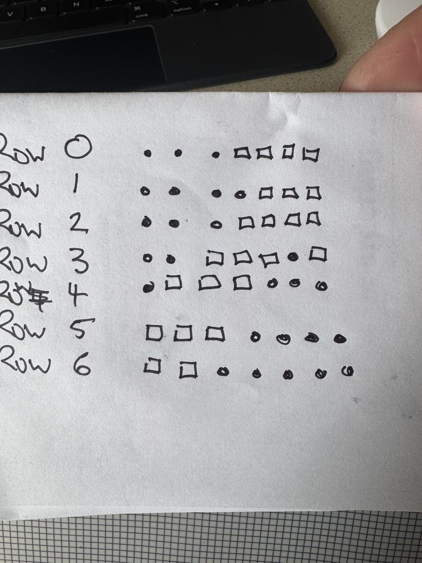
Some of those small details took more work than you'd expect. The climb and descend arrows are a good example — rather than using a generic symbol, each one was hand-drawn pixel by pixel on graph paper first, checking how a handful of lit squares would actually read at real size on the panel before a single line of code got written.
Where it's heading
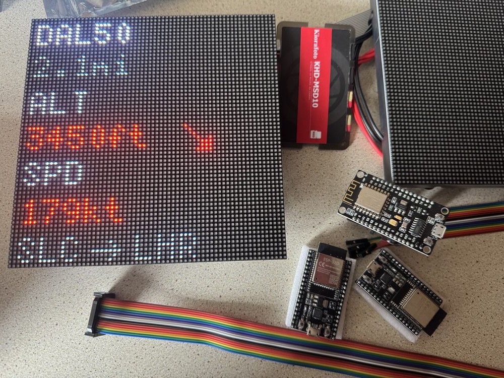
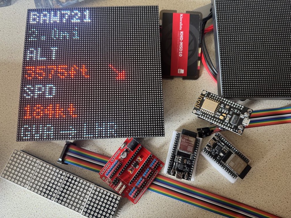
The current build (a full Raspberry Pi plus a bonnet) is the flagship version — but it's not the cheapest way to get a SpotterBoard running. That's the thinking behind SpotterBoard Lite: a stripped-down version built around a single ESP32 chip instead of a full Raspberry Pi, wired directly into the same style of LED panel. No SD card, no operating system to manage — just a small, inexpensive board doing one job well. It's still early, but the core wiring and driver library have already been worked out on the bench.
Making it real
Alongside the hardware, SpotterBoard's been going through the more grown-up motions of becoming an actual project rather than just a personal build: a UK trademark application under the SpotterBoard name, and a genuine visual identity — the orange, the pixel-radar mark — worked out together with Ralph rather than bolted on as an afterthought. The project actually started out under a different working name, FlightMatrix, before settling on SpotterBoard ahead of launch.
None of that changes what it fundamentally is, though: a small screen that tells you what's flying over your house, built because a phone app doing the same thing just isn't as satisfying as watching it happen in glowing pixels on your own hardware.